Patented and Powerful
| |
|
|||||||||||
| |
|
|
|
|
|
|
|
|
|
|||
| |
||||||||||||
| |
Patented and Powerful |
|||||||||||
| |
||||||||||||
| |
||||||||||||
| |
|
||
|
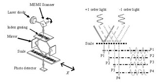
NanoWave's Scanning Probe Position Encoder (SPPE) technology offers many advantages over other encoder technologies. Even laser interferometers and capacitance sensors are unable to match the resolution and performance specifications on an SPPE. Scanning Probe Position Encoders (SPPEs) are, in some ways, similar to other non-contact, reflection-based, optical encoders. Laser light is projected onto a diffraction grating used as a measuring scale. The reflected light is collected in the encoder head and converted via a photo diode cell into one or more electrical signals for further processing. |
 |
||
|
The most important principle of an SPPE is that the laser light is oscillated rapidly (i.e., scanned) with very small amplitude on the grating scale. The direction of the scanning is the same as the direction of the measurement of interest. This creates a high-frequency modulated signal, even when there is no motion. When motion does occur this modulated signal undergoes phase shifts and changes in shape (please watch the video of the actual signal coming out of our SPPE-1000 head). After Analog-to-Digital conversion (at a rate ranging from 50 to 200 MHz), position information is extracted from this complex signal using NanoWave's proprietary signal processing algorithms. These algorithms are implemented in firmware in a high-speed FPGA in our SPPE products to insure low latency and high signal bandwidth. These algorithms employ a phased locked loop and examine the higher harmonics and phase changes in the received signal. Therefore, SPPEs are insensitive to drifts in the light intensity and other noise sources at lower frequencies. The FPGA environment also provides flexible digital filtering mechanisms for effective noise elimination at higher frequencies.
|
|||
|
|||
Compared with conventional two phase output position encoder, SPPE thus produces a single phase output for the position detection. This enables superior interpolation error (linearity) since fine adjustment of the signal amplitude, DC offset, exact 90-degree phase difference between the two phase output signal is no longer necessary. This in tern allows the usage of the low cost and durable scale selection. There is, of course, a trade-off between resolution (defined as RMS noise) and signal bandwidth governed by the inherent noise spectrum of the opto-electronic system. This is true in any encoder. However, because the laser light is scanned at high-frequency (~ 200 KHz) and even higher speed digital electronics processing the signal, SPPEs can attain both superior signal bandwidth and superior resolution, while also tracking motion at high velocities and accelerations due to its patented multi-frequency synchronous phase tracking position detection. The output of the FPGA is a 40-bit word (parallel or serial) representing the position measurement. In effect, the algorithms in the FPGA serve as both interpolator and counter. It also provides for clock synchronization with the customer's servo controller for fast and accurate motion control. These design principles enable high-performance at low cost, since very few components are involved and since larger pitch gratings can be used to attain very fine resolutions. For instance a grating with a 5 micron pitch can be used to attain resolutions as fine as 10 picometers. This contrasts other technologies that require gratings with ~500 nanometer pitch (10 times smaller) to attain resolutions on the order of 50 to 100 picometers (when examining the noise level). |
|||
| © 2000-2010 NanoWave Inc. NanoWave is a registered trademark, NanoWave Inc. All other trademarks are the property of their respective owners. All technology described herein is patent protected. |
|||
| |
|||